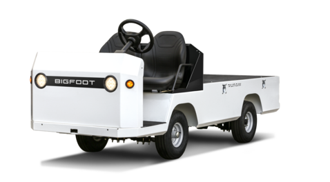
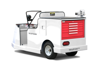
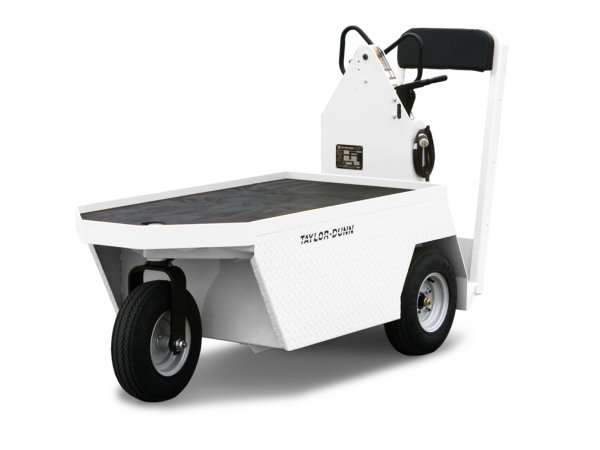
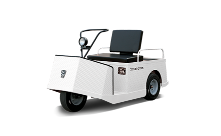
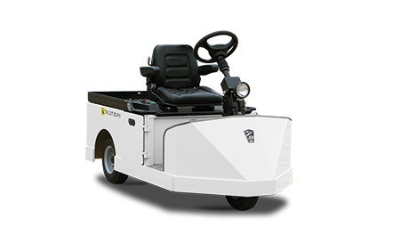
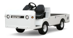
The information in this article applies to standard Bigfoot and Bigfoot XL vehicles – model numbers B5-440-36, B5-440-48, B5-540-48XL and BF-030-48. Note that vehicle customization may cause variation from the information in this article.
Shown below is a Bigfoot XL Taylor-Dunn utility vehicle.
VEHICLE CONTROLS
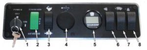
1. Start Switch: The start switch turns on the vehicle electrical control system. This switch may or may not require a key to operate.
Rotate the switch clockwise to turn the vehicle system ON and counterclockwise to turn the vehicle system OFF.
The switch should be in the OFF position whenever the operator leaves the driver’s seat. This switch is designed to secure and disable the vehicle. The key can only be removed when the switch is in the OFF position.
Note: All electrical devices including lights, horn, etc. will not function unless the switch is ON.
2. Directional Control Switch: This switch determines the direction of travel. Your vehicle will have one of two types of switches, depending on when it was manufactured.
The rocker switch shown in the dash illustration above has three positions:
- FORWARD: Push the top of the switch all the way in to travel forward.
- REVERSE: Push the bottom of the switch all the way in to travel in reverse.
- OFF: The center position between forward and reverse is the “direction” OFF position.
The OFF position does NOT turn the vehicle control system OFF. Use the start switch to turn the vehicle control system OFF. Refer to start switch entry in this section for details regarding turning the vehicle control system off.
3. Hi-Low Speed Switch: Push the bottom of the High/Low switch (turtle) for slow vehicle speed. Push the top of the switch (rabbit) for normal speed.
4. USB Port: This port allows the vehicle operator to charge devices (for example, a smart phone or tablet). The dual-port design is capable of charging two devices at the same time. Note that the port is only active when the start switch is ON.
5. Dash Display: The Smart View Display (SVD) Indicator is shown below. Depending on your vehicle’s specifications, one of two available dash displays will be installed in this location.
The Smart View Display (SVD) functions as a Battery Status Indicator (BSI), hour meter (HM), speed controller status monitor and as an optional maintenance monitor feature. The operation of each of these functions is described below.
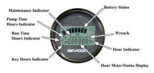
Battery Status Indicator: A bar graph representing the current state of charge is located across the top of the display.
When the batteries are fully charged, all segments of the bar graph will be on. As the batteries are used, segments will turn off from right to left.
When the batteries are discharged to 75 percent (25 percent battery remaining), the last three segments will flash, indicating that you are approaching the end of the battery cycle. At this time, the vehicle’s batteries should be charged as soon as possible.
At 90 percent (10 percent battery remaining), all segments will flash and the vehicle’s speed will be reduced. At this time, the vehicle should be removed from service for charging. Discharging beyond 90 percent will result in damage to the batteries that will shorten the battery life span.
Note: The BSI will only reset to full after a full charging cycle has completed. In addition, the BSI will not reset to full unless the battery is discharged below 75 percent before starting the charge cycle.
Hour Meter: The hour meter has three functions: Key Hours, Run Time Hours and Pump Hours. One of these three functions will be displayed whenever either of the Hours Indicators are visible at the right side of the display.
Key Hours: This icon represents the silhouette of a key and indicates the accumulated length of time in hours that the key switch is in the ON position. When the display is turned on, the Key Hours will be displayed for approximately 5 seconds as indicated by the Key Hours Indicator located at the lower left of the display.
Pump Hours: This icon represents a motor symbol with a “P” in the center and indicates the accumulated length of time the hydraulic pump has been in operation. This is an optional feature. After Key Hours, the Pump Hours will be displayed for approximately 5 seconds as indicated by the Pump Hours Indicator located at the lower left of the display.
Run Time Hours: This icon represents a motor symbol with a “T” in the center and indicates the accumulated length of time that the vehicle has been in operation. Time is accumulated when the FS-1 switch in the accelerator module is closed. After the Pump Hours, the Run Time Hours will be displayed as indicated by the Run Time Hours Indicator located at the left of the display.
System Fault Monitor: The display will indicate a fault code whenever the control system logic detects a problem with the control system. A fault code is displayed whenever the Fault Code Indicator (the letter ‘F’) is visible at the left of the numeric display. Refer to the fault code table in your Vehicle Operator and Service Manual or read Taylor-Dunn Fault Codes for descriptions of the fault codes.
Maintenance Monitor: The Maintenance Monitor function is optional. The Maintenance Monitor function can be turned on or off by your dealer. Contact your Taylor-Dunn Dealer to enable or disable this feature.
Operation: The SVD notifies the operator 10 hours (standard) before a scheduled maintenance is due. During this warning period, the meter will continue to alert the operator. This should allow sufficient time for the operator to schedule the maintenance that is due with minimal downtime. If the scheduled maintenance is not performed before the warning period elapses, the vehicle’s maximum speed will be significantly reduced.
Warning Period: The warning starts when the Maintenance Indicator is ON and the Wrench icon is flashing. The Wrench icon will continue to flash until the warning time has expired.
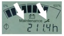
Maintenance Due: Once the warning has expired and the maintenance is due, the Wrench icon will stop flashing and remain ON. Additionally, the vehicle’s maximum speed will be significantly reduced until the maintenance is performed and the display is reset. The display should only be reset by an authorized technician. Refer to the illustrated parts section of the Vehicle Operator and Service Manual for information regarding tools required to reset the Smart View Display.
Speed Controller Status: The display will indicate a fault code whenever the control system logic detects a problem with the control system. A fault code is being displayed whenever the Fault Code Indicator (the letter ‘F’) is visible at the left of the numeric display. Read Taylor-Dunn Fault Codes for more information.
Refer to your Vehicle Operator and Service Manual for more information.
6. Headlight Switch: Push the top of the headlight switch to turn the lights ON. Push the bottom of the switch to turn the lights OFF.
7. Windshield Wiper Switch: The windshield wiper switch is optional.
- Standard Bigfoot: Push the top of the wiper switch to turn the wiper ON. Push the bottom of the switch to turn the wiper OFF.
- Bigfoot Deluxe Cab 2-Speed Wiper: Push the top of the switch to first position for SLOW and to second position for FAST. Push the bottom of the switch all the way in to turn the wiper OFF. Below the switch is a button (not shown) to operate the window washer.
8. Strobe Light Switch: The strobe light switch is an optional feature.
Push on top of the strobe light switch to turn the strobe light ON. Push the bottom of the switch to turn the strobe light OFF.
OPERATOR CONTROLS
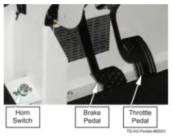
Throttle Pedal: The throttle pedal is located to the right of the brake pedal. It controls the speed of the vehicle and operates like the throttle pedal in an automobile.
Depress the pedal to increase speed and release the pedal to decrease speed.
Foot Brake Pedal: The foot brake pedal is located to the left of the throttle pedal. This pedal is designed for operation with the driver’s right foot. It works like the brake in an automobile.
Applying pressure to the brake pedal slows the vehicle according to the amount of pressure applied. Relieving pressure from the pedal releases the braking action. Pressing the brake also activates a higher level of regen.
Horn Switch
The horn switch for this vehicle was designed to be activated using the operator’s foot. The foot horn switch is located to the left of the foot brake pedal. To activate the vehicle horn, press the foot horn switch with your foot.
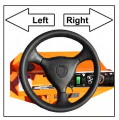
Steering: The steering wheel and steering system are like an automobile. To turn right, turn the steering wheel clockwise. To turn left, turn the steering wheel counterclockwise.
Turn Signal Switch
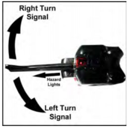
The turn signal switch is an optional lever, located on the left side of the steering column. PULL the lever up to activate the right turn signal and PUSH the lever down to activate the left turn signal. The switch is not self canceling. You must return the switch to the center OFF position after the turn is completed.
Hazard Light Switch: The hazard light switch is located on the turn signal switch. The switch is a small tab or knob under the turn signal lever.
To activate the hazard lights, PULL the tab out. To turn the hazard lights off, you must activate the turn signal switch.
Emergency Power Cut Switch
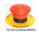
The emergency power cut switch should be used if the vehicle starts to operate in an unexpected manner or if there is an odor or sound that may indicate an overloaded electrical circuit. If any of the above occurs, immediately and safely pull to the side of the road and stop. Then push on the switch knob and exit the vehicle. Do not re-engage the switch until the vehicle has been inspected by a qualified technician.
The emergency power cut switch should only be activated if the vehicle must be stopped. Do not use the switch when only parking the vehicle.
The location of the switch will vary depending on vehicle configuration. The switch is a large red knob located within reach of the driver. The illustration above shows a typical power cut switch knob.
Pull up on the knob to re-engage.
Park Brake, Manual
The manual parking brake is standard on Bigfoot Models.
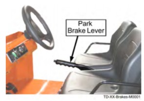
The park brake is actuated with a hand lever. To set the park brake, push down on the brake pedal and pull the lever back firmly. To release the park brake, press the foot brake pedal, push the button on the end of the handle, then push the handle forward and downward until it stops.
Park Brake, Automatic Electric
The automatic electric park brake is standard on Bigfoot XL and optional on the Bigfoot.
The automatic electric park brake will be applied whenever the vehicle is not in motion. While coasting or using the foot brake, the motor speed control monitors the motor rpm and the park brake will be applied after the motor stops rotating.
The automatic electric park brake will be applied when the driver gets up off the driver’s seat. If the driver gets off the seat while the vehicle is in motion, the vehicle will rapidly decelerate and then apply the park brake.
Refer to the Towing This Vehicle section of the Vehicle Operator and Service Manual for information on temporarily disabling the automatic electric park brake.
Warning: The park brake should be disabled for servicing or towing procedures only. Do not operate the vehicle while the automatic park brake is disabled. Operating the vehicle with the automatic park brake disabled could lead to severe bodily injury and/or property damage.
Windshield Washer: This is found on Deluxe Cabs only.
The windshield washer switch is located on the dash below the wiper switch. Press the switch to spray washer fluid on the windshield. The washer reservoir is located under the frame below the driver seat. Access the reservoir by moving the seat forward.
For more information, refer to your Vehicle Operator and Service Manual.
To service your vehicle, see an authorized Taylor-Dunn Dealer. To find a dealer near you, use the Dealer Locator.
